At this year’s Carleton Hackathon, my friend and I decided that we wanted to build something with which both of us could show off our strengths, as well as learn something new from each other. Him specializing in frontend development and myself in embedded systems, we chose to build a smart power outlet. I would be responsible for the electronics and device firmware, while he would whip up a fancy web interface for interacting with the devices. Two more friends joined our team to accomplish these tasks in 24 hours.
Of course, smart power outlets are nothing new. Along with smart lights, they’re the first things that spring to mind when you think of Alexa taking control of your home. We knew that ours had to be different, so we focused on two principles to make it stand out.
- Build it from scratch
- Add network/multi-device oriented features
Step 1: Building the basics
Building it from scratch allows us to have absolute control over the root functionality of the device. Want to include LED indicator strips for viewing network power consumption? Done. (More on that later) It also means that we don’t have to reverse engineer or create hacky APIs for proprietary equipment, as most off-the-shelf smart power outlets are not very developer friendly. The requirements for this board were relatively simple:
- Communicate to the cloud/control the outlet over wifi
- Measure AC power
- Switch the power ON/OFF
- Some sort of local indicator for device and network power metrics
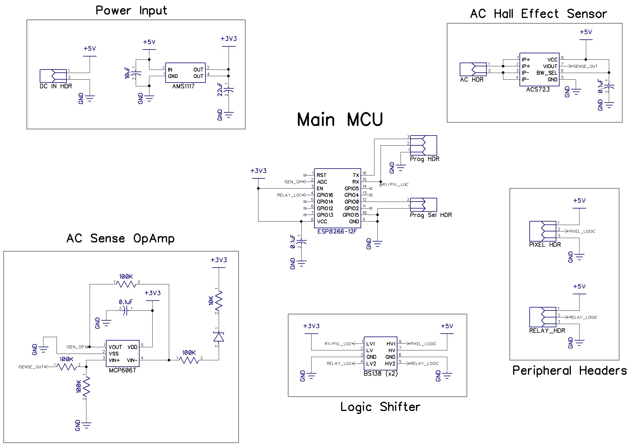
Any time I have a project that requires WiFi, my first choice is always the ESP8266 module. They’re dirt cheap and have plenty of Arduino libraries, which means less time configuring and writing boilerplate code and more time working on your application. A hall effect sensor (ACS723) is used to measure the AC current. It measures zero to five amps AC or DC and outputs an analog voltage at 400mV/A. By sampling this voltage at a much higher frequency than the 60Hz AC waveform, one can determine the maximum and minimum amplitudes and compute the RMS current. Unfortunately the ESP8266 only has a 10-bit ADC. To increase the resolution I used an op-amp circuit to shift the voltage so that only a half-wave is measured, doubling the effective resolution.
Circuit Schematic
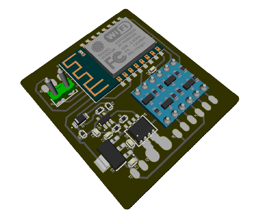
Board Render
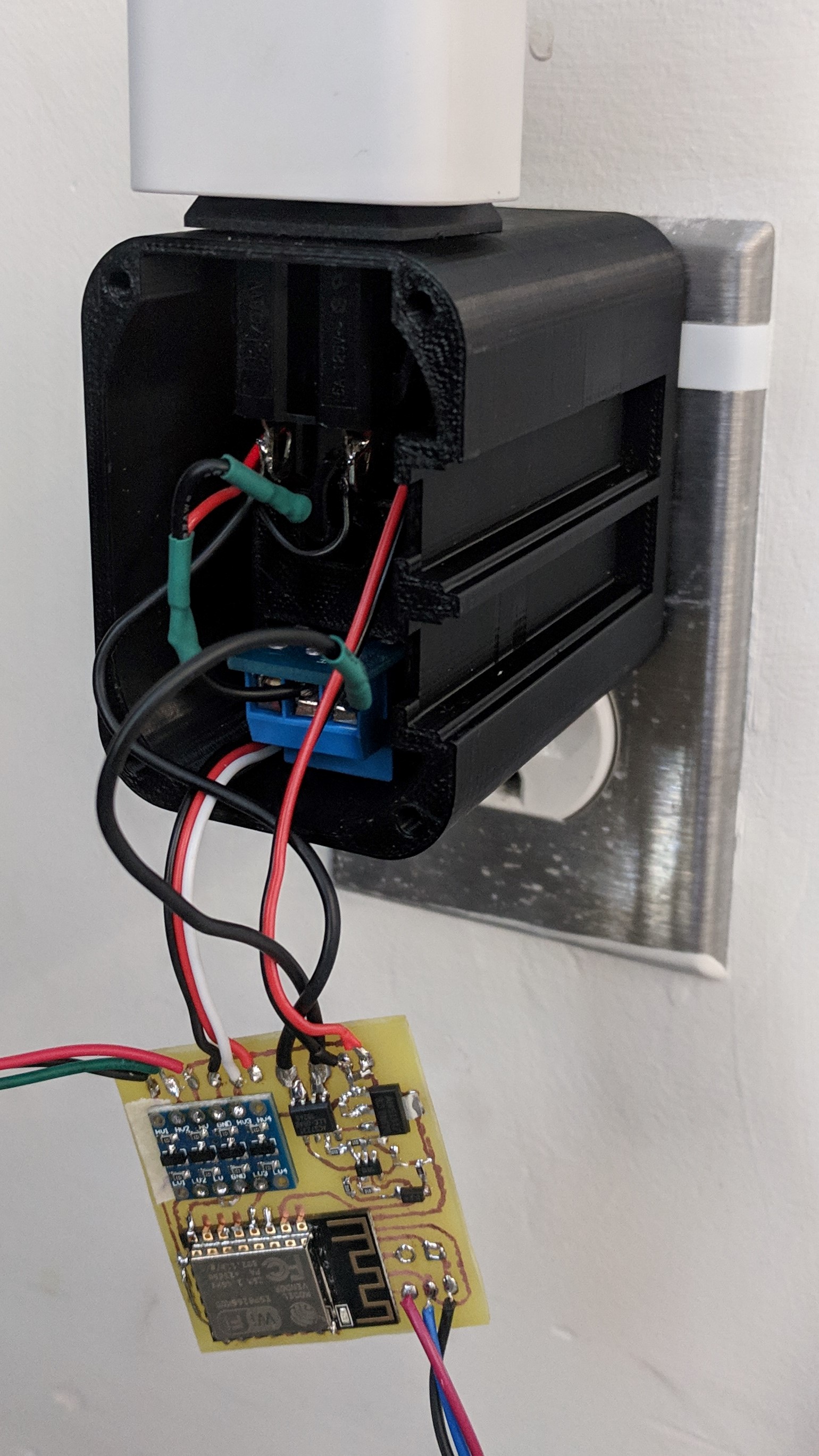
The board was made using the tried and true laser toner etching method, which involves transferring the design onto a copper board in the form of laser printer toner and etching away the remaining copper with an aggressive solution of hydrochloric acid and hydrogen peroxide. Others have had great success with this method, but it took me a half-dozen tries to get a usable product. Off the shelf parts include an AC switching relay and 5v AC/DC transformer. Also off the shelf are two strips of neopixels, designed to provide the user with an indicator of device power draw and total network power draw. The neopixels are individually addressable RGB leds, providing a good opportunity to get creative with indicating a wide range of device and/or network power information.
The housing was designed in Fusion360 and 3D printed while the competition took place. The decision to go with a custom PCB really payed off as we were able to significantly reduce the housing volume, and our smart outlet is not much bigger than what’s currently available on the market.
Step 2: Features you didn’t know you needed…
The addition of features oriented towards managing power consumption in larger deployments aims to fill a gap that currently exists in the market. Most consumer smart power outlets these days can measure individual power consumption, but lack larger scale analytics or management software for groups of these devices. These features may exist in industrial solutions, but are out of reach for the vast majority of consumers or smaller businesses. One of the key features of our smart outlet is the ease of use any granular control over larger deployments. Simply by plugging it in and associating a wifi network, the device will provision a ‘virtual group’. Any other devices which join that wifi network automatically join the same group. Virtual groups can be modified to create arbitrary groups of devices even spanning multiple physical networks.
With this group-based management scheme, it allows you to do some pretty cool things. You can define group power limits and apply rule-based device power switching when these limits are met- an example is grouping hospital electronics by their usage priority. If there is a power outage resulting in reduced power capacity, safety-critical devices can continue running while auxiliary electronics are automatically switched off to save power. The advantage of the smart outlet is that it’s much faster, cheaper, and more portable than manually wiring a building to achieve the same effect.
Techno-garble
We built our backend with Flask, a python framework for web apps. It, along with the MQTT broker, reside in Google cloud platform instances provided for the hackathon. Vue.js and bootstrap are used for creating the web dashboard and visualizing data trends.

For our efforts we ended up winning the grand prize at CuHacking 2019! Wouldn’t have been possible without the rest of the team.