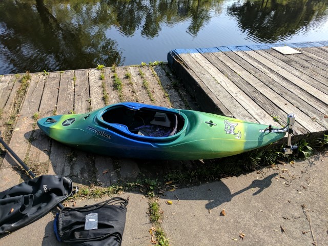
A new Beginning
Last summer I picked up a kayak hull with intentions of turning it into an ekayak. Judging by some of my previous posts on hackaday, it could be assumed that this project is well and truly dead. However, one year later I have decided to take a second shot at building an e-kayak that actually works. While last year’s design serves as a proof of concept, it suffered from many shortcomings, mainly rooted to the fact that the suite of rc electronics used were woefully underpowered. It was pretty naive to think that I could push even 600-700 watts continuously at a supply voltage of 7.4V. Electronics are limited in their usable energy output by the amount of thermal, or waste energy that they can dissipate. Given some device with a fixed internal resistance, the voltage drop across it is proportional to the current flowing through it. The heat output, or power lost, is then given by $ P = v*i $ or $ P = i^2/R $. It’s important to realize that the overall voltage of the system has absolutely no bearing on the voltage drop across components, so long as the current stays the same. For this reason, the easiest way to make a system more efficient is to increase the voltage and decrease the current. The overall output power stays the same, but doubling the voltage and halving the current will result in ¼ of the heat. Europeans obviously figured this out when they chose to make 240V the standard household voltage, rather than 120V in North America.
With this in mind, here are the new electronics to power the kayak:
- YEP 120A High Voltage ESC
- Turnigy 6374 168kv Brushless Motor
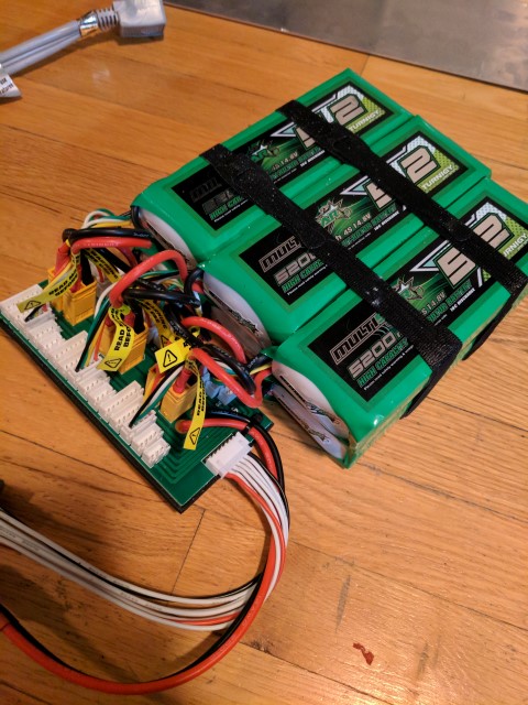
- 6x 4S 14.8V 5.2Ah Multistar Lipo Batteries
The batteries are wired in 3S2P configuration, giving me 12 cells for a peak voltage of 50.4V and capacity of 10.4Ah or around 500Wh. 500Wh is equivalent to about 70 iPhone 7 batteries, but only 0.5% of a Tesla P100D battery pack. If anything this makes you realize just how massive the batteries in Tesla cars are.
The YEP ESC from Hobbyking was chosen because it’s a shameless clone of the more expensive, German designed YGE ESCs. The open source VESC was also a serious consideration due to it’s telemetry and multiple control options (i2c, canbus, ppm) but in the end the YEP ESC has beefier mosfets and is rated at higher current. 120 amps continuous is overkill, but since I’m using it in a waterproof enclosure I don’t want to run into issues with thermals, so some margin is good.
The Turnigy 6374 motor is the weakest link in this group, being rated at 2400W and 80A peak. Nonetheless, it’s a popular choice for DIY electric bikes and skateboards, so we’ll see how it performs in the kayak. It’ll be important to find a good gear ratio to match the prop and get the maximum performance. In the next post I’ll talk a bit about basic brushless motor theory and how it applies to this build.
Brushless Motor Theory
Brushless motors have always seemed very complicated to me, but after a bit of research I think I understand the basics. The type of brushless motors used in remote control vehicles and most applications below a few kW have a permanent magnet in the rotor which interacts with the electrical field generated by 3-phase AC electricity in the stator. The windings are placed 120* apart, and fire in clockwise or counterclockwise sequence. When the electrical field is created in the stator, it causes the magnet in the rotor to align with it. Unlike an induction motor, which requires some degree of slip between the rotor and stator to generate torque, permanent magnet brushless motors don’t slip at all (unless they torque stall). This means that one can precisely control the motor rpm by controlling the frequency of the AC current. For example, if you were to plug such a motor into a household socket with a frequency of 60Hz, the motor would spin at exactly 60 cycles per second or 3600 rpm. Many utility motors function like this, requiring a change in gearing to change the output rpm.
This fixed-rpm operation is obviously impractical for any vehicles. Instead, an electronic speed control is used as the middle-man between the battery and the motor. Essentially, all an ESC is, is a variable frequency inverter, which inverts the DC from the batteries into 3-phase AC for the motor. So if motor rpm is simply controlled by frequency, what does voltage control? This is where my understanding drops off a little, but I’ll try to explain.
Whenever the rotor turns, there is some resistive force. This force is the torque on the motor. Even when the motor isn’t connected to anything, the friction in the bearings created some force that opposes the motion of the rotor. The current drawn is simply a function of applied torque and magnet strength. Since the strength of the magnet cannot be changed after manufacturing, this means that motor torque is the only variable controlling the magnitude of current. However, unlike brushed motors which are fed by DC, synchronous motors are fed by AC and therefore voltage and current are both sine wave functions. The phase angle between these two determines the real and imaginary components of current, representing useful torque and magnetic flux respectively. Let’s look at some phasor diagrams:
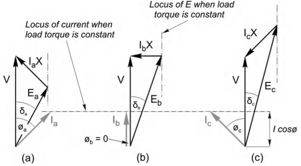
Hughes, A. and Drury, B. (2013). ELECTRIC MOTORS AND DRIVES: Fundamentals, Types, and Applications. 4th ed. Oxford: Elsevier, p.289.
The equivalent voltage equation for a motor is $ V = IR + IX + E $, but we can drop IR for simplicity, leaving us with $ V = IX + E $, where IX is the voltage drop due to the inductance of the windings, and E is the back EMF generated by the spinning magnet rotor. Two important considerations:
- Due to the inductive nature of the windings, voltage IX always leads current I by 90*
- E is proportional to magnet strength and rotor speed
As you can see in the phasor diagram, input voltage is equal to the vector sum of IX and E. If E is smaller or larger than V, the direction and magnitude of IX also changes. Recall that voltage IX leads the current by 90*, so any change in the direction of IX is reflected in the phase angle of current I. Figure (a) and (c) show the underexcited and overexcited cases respectively. In both of these cases, the current vector is composed of torque and magnetic flux components. The cosine of the angle between voltage and current is also known as the power factor and is a measure of motor efficiency. Figure (b) represents the ideal condition, where the real components of V and E are identical. The current is in phase and has only a useful torque component. The power factor is 1 and peak efficiency is achieved.
From this we can conclude to maintain peak efficiency, the input voltage must be set to match the back EMF. Since we’re dealing with a permanent magnet, the back EMF is a function of magnet strength and rotor speed, the latter which is set precisely by the supply frequency. So that explains how voltage and rpm are related. Not such that rpm is dependant on voltage, but that voltage is varied to give maximum useful torque at a given rpm.
Sidenote: I imagine that when Tesla talks about removing the battery heaters in the model 3 and just relying on using the motor to heat the batteries, they are manipulating the current vector so it generates heat instead of torque to the wheels.
Anyways, the opposing torque created by the prop is proportional to the speed at which it turns, so at steady state, the faster it turns, the more current should be drawn by the motor. It will be important to find a gearing so that the motor draws appropriate current from the ESC at a given speed. At full speed, (8440 rpm at 50.4V) the motor should have a continuous current draw of about 50 amps to reach it’s intended power limit of around 2.5kW. (50.4V x 50A) Also, given the motor’s KV rating of 168 rpm/V, we can solve for shaft torque at a specified current, because torque constant Kt is simply the inverse of KV.
At 50A this results in 2.84 Nm. This figure can be checked by calculating power output:
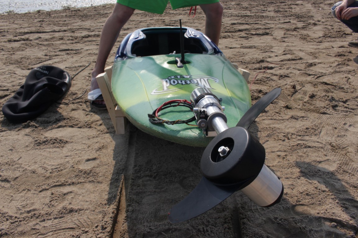
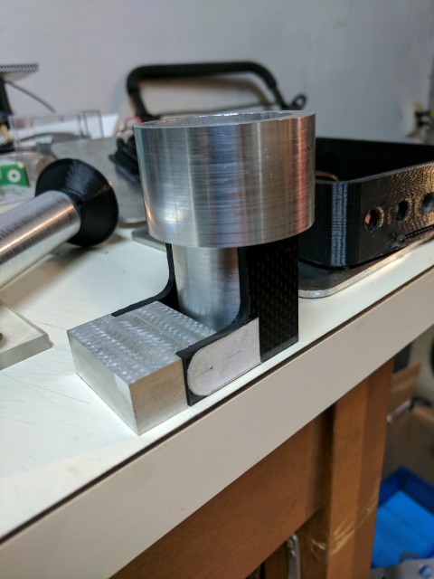
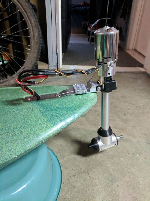
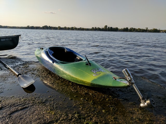
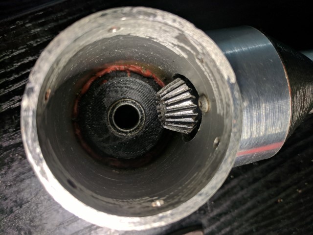
Outboard Build
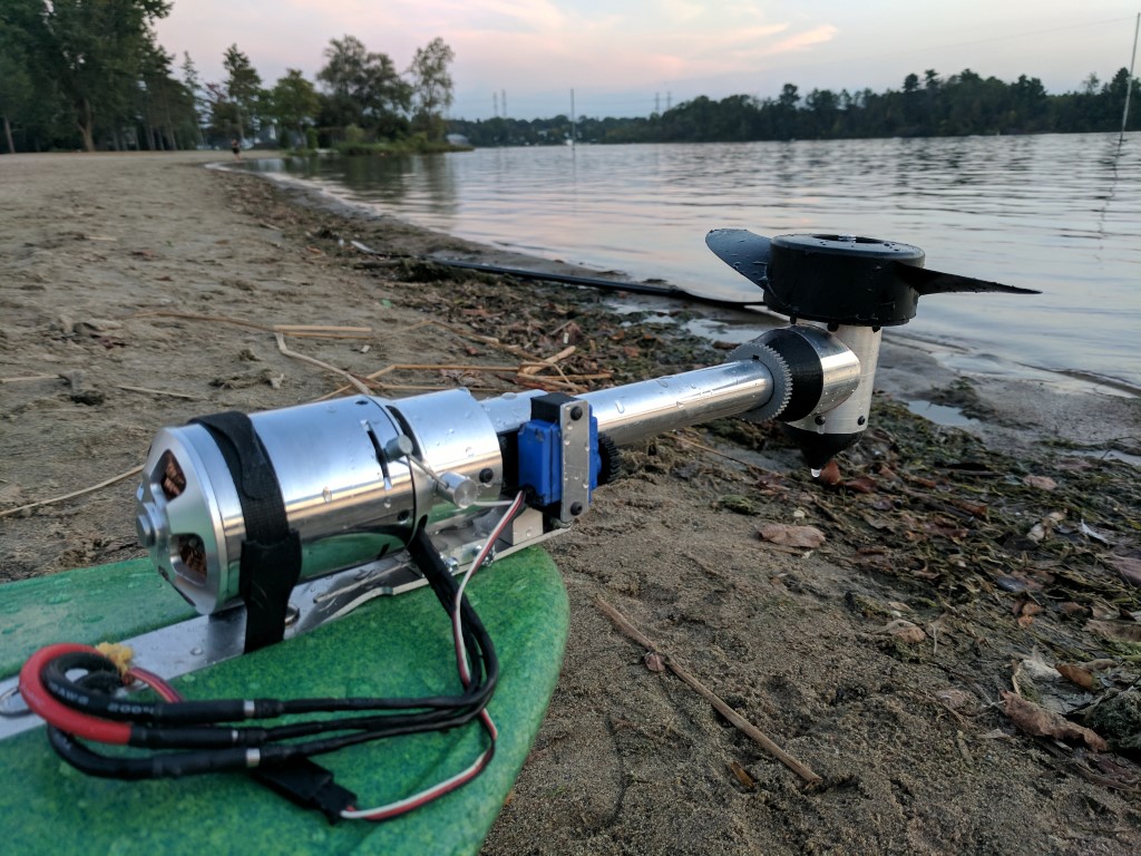
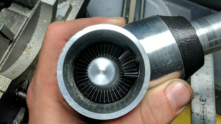
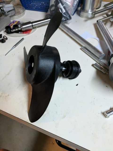
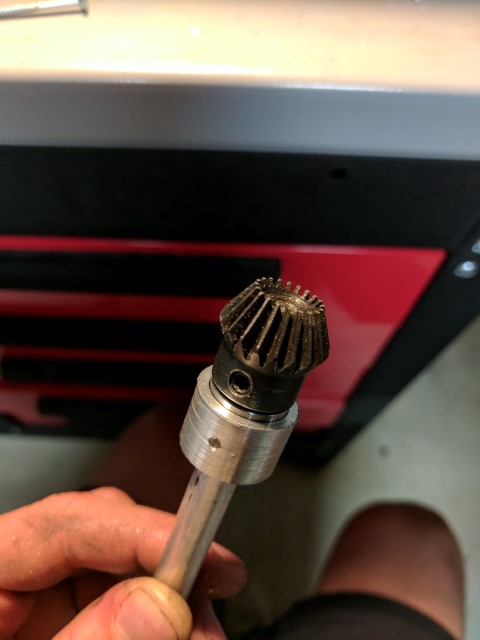
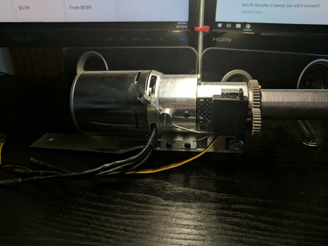
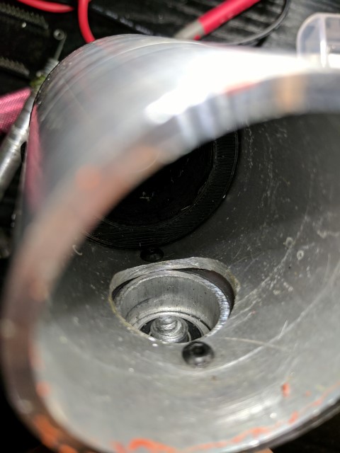
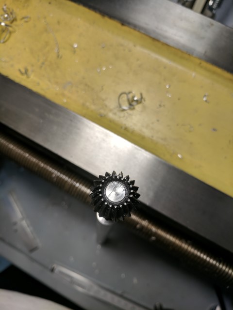
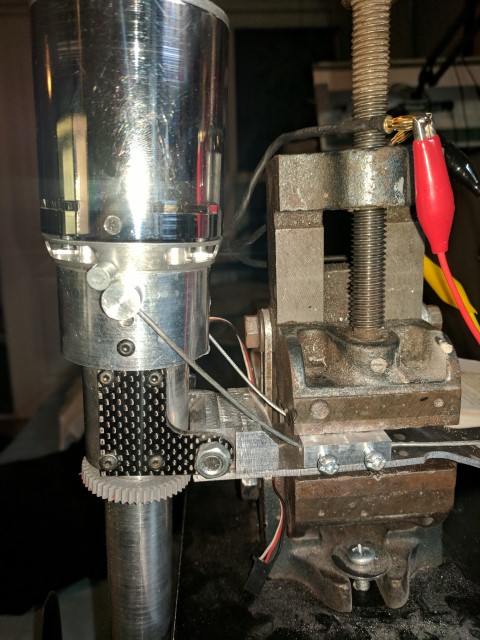
Top: Taken after the first successful test run. Bottom: Bevel gear set transmits power to the prop.
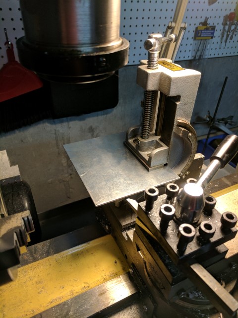
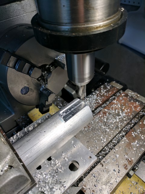
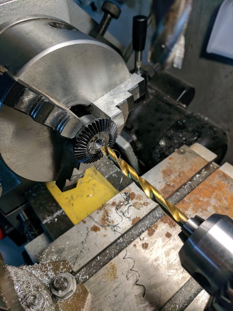
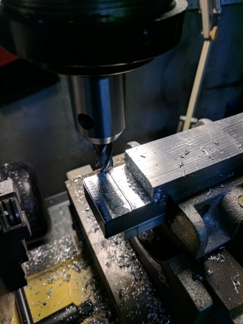
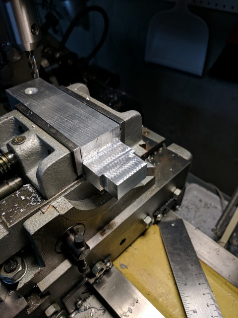
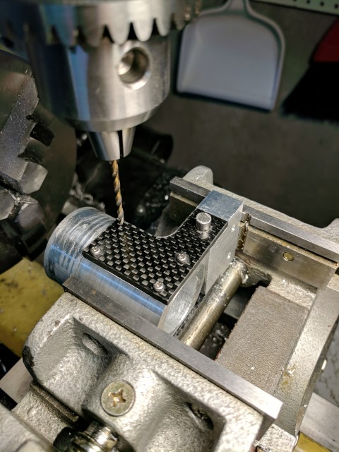
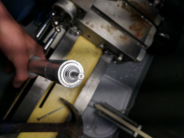
The new outboard more closely resembles a traditional outboard engine with the motor above water level, connected to the propeller through a vertical driveshaft and a 90* bevel gear set. This allows me to have a 2:1 gear reduction through the bevel gears and also keep the motor out of the water. Unfortunately I lose water cooling, but it gives me the piece of mind of a dry motor that won’t get banged up by rocks or other stuff in the water. Most of the components are built out of 6061 aluminum. I’m lucky to have access to a manual mill and lathe; without it this project would have been pretty much impossible. The parts in black are 3D printed from PLA. Apparently PLA can break down in water due to its biodegradable nature, but I haven’t had any issues. The lower drivetrain is sealed from water and features a stuffing box filled with axle grease at the prop shaft output. This has kept most of the water out, but I believe I need to reseal some of the screw holes to make it 100% watertight. Radial bearings are used throughout the driveline and there is a thrust bearing inside the back endcap which transmits the thrust force of the prop shaft to the rest of the outboard.
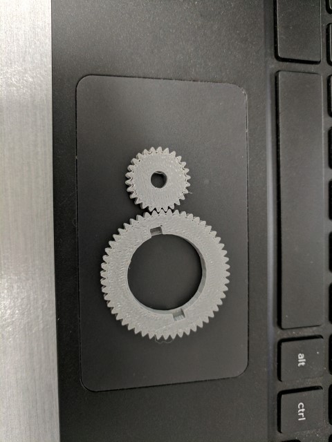
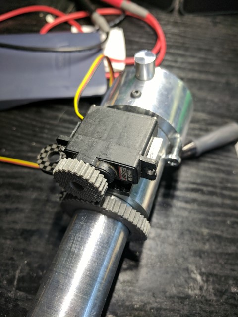
Steering duties are taken care of by a micro servo and a 3D printed gear set. Eventually it might be nice to have a 360* servo, but this introduces problems with determining the exact angle of the outboard because you lose position feedback. For now +/- 45* of throw is sufficient.
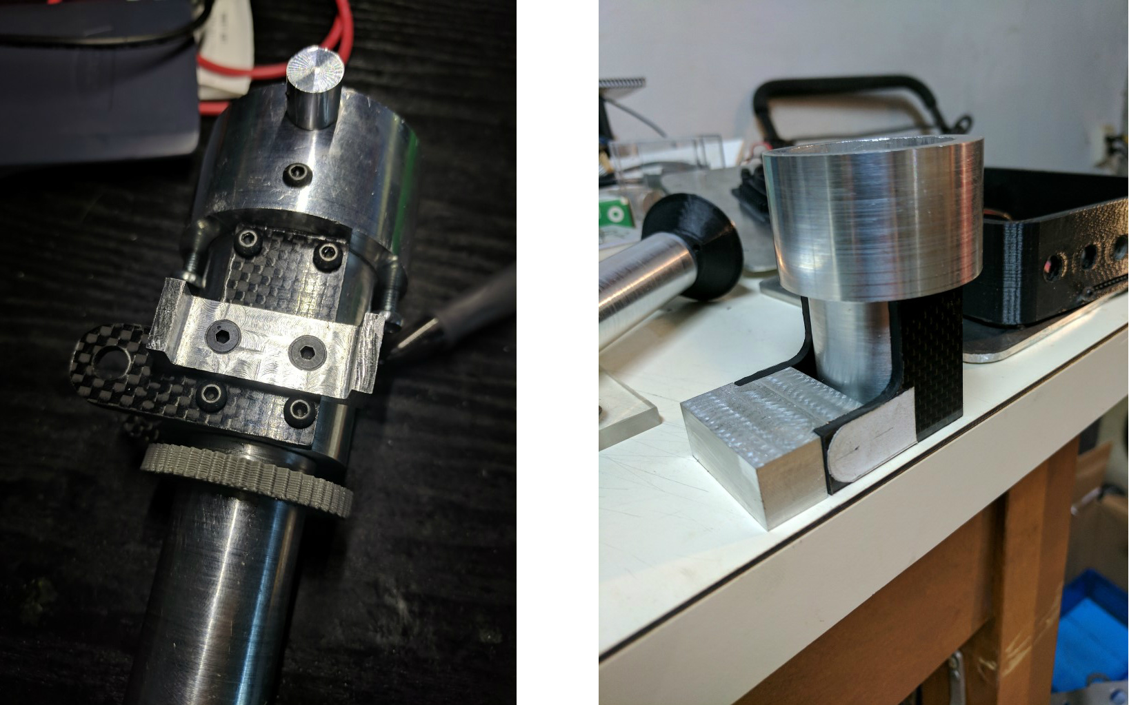
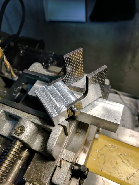
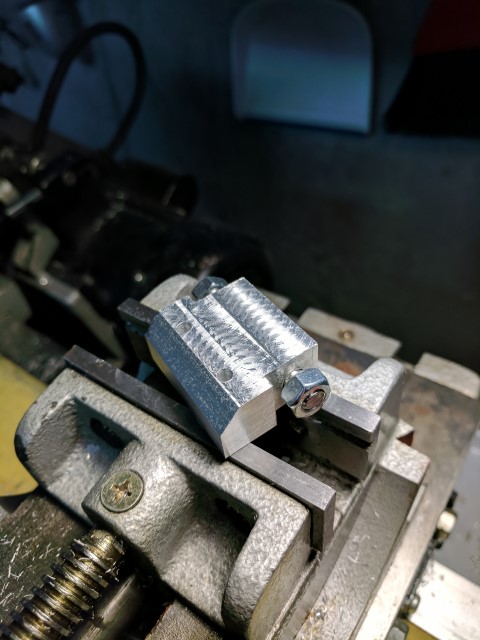
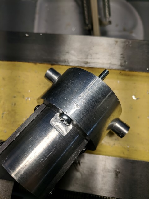
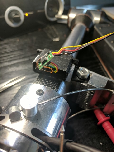
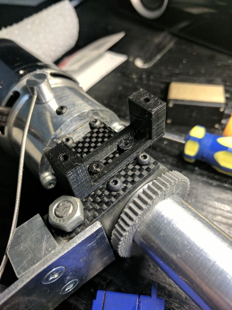
Left: V1 steering servo mount. Right: Connection between the pivot block and outboard assembly.
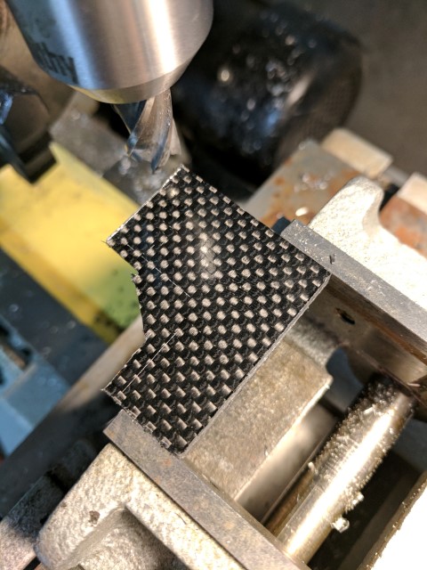
I liked the ability to flip the entire outboard assembly up in the previous e-kayak build, so I carried it over to this one. However, gone is the janky cabinet door hinge, replaced by a solid block of 6061 that holds a steel pivot pin, threaded on both ends. Carbon fiber plates are used to hold the outboard assembly to the mount. This setup has reduced play to being basically non-existent. It will be interesting to see how it copes when the boat is turning and the direction of thrust force is not perpendicular to the pivot pin, because this will cause some nasty twisting moments in the assembly.
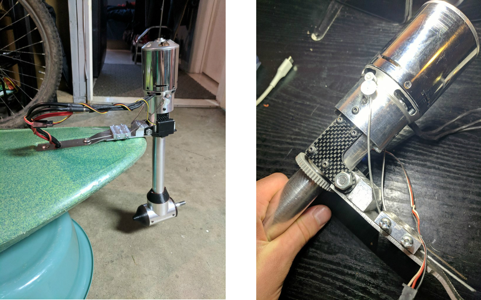
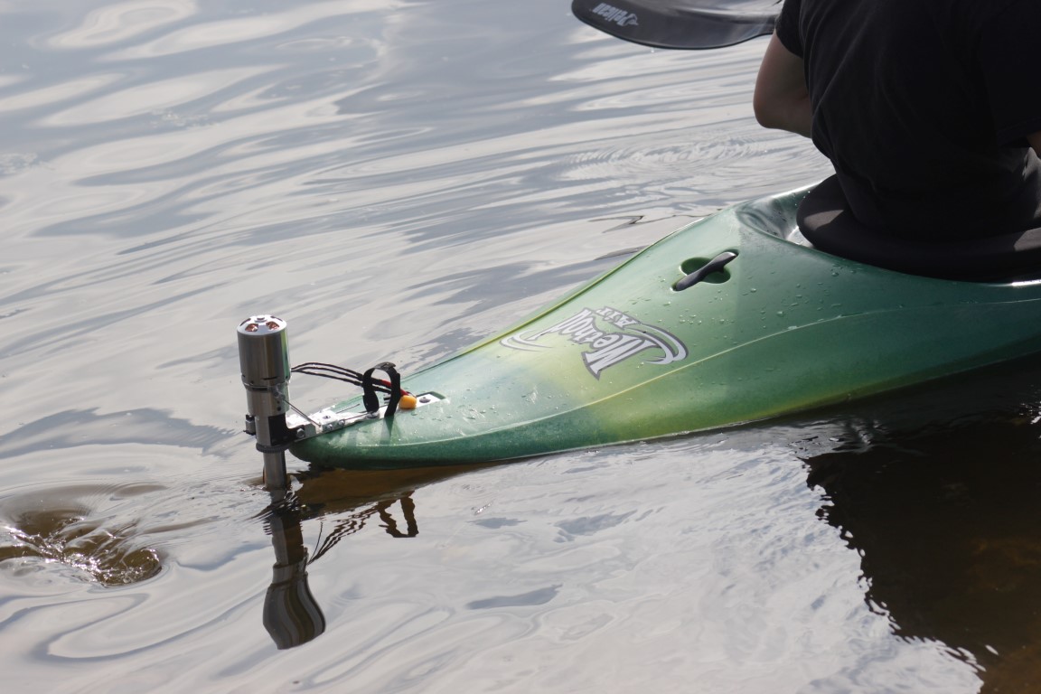
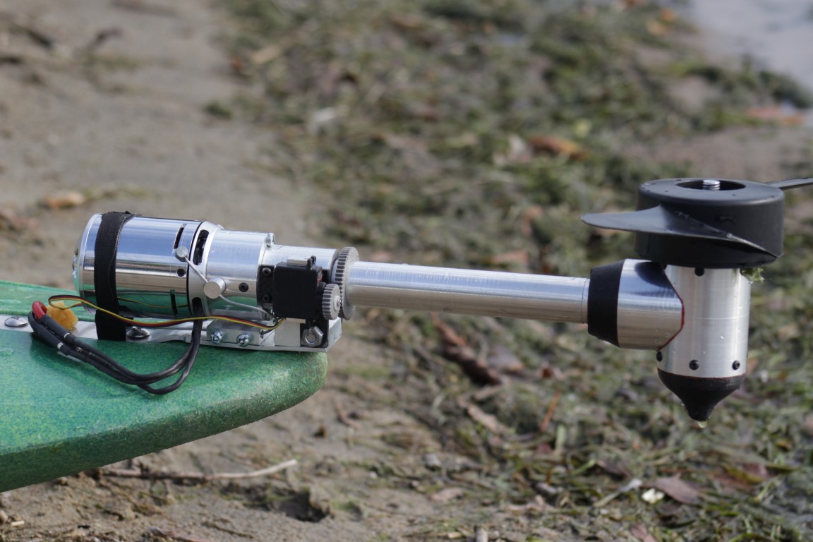
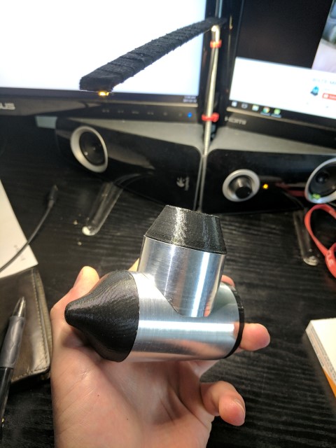
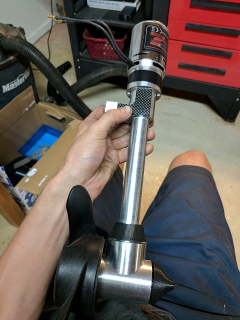
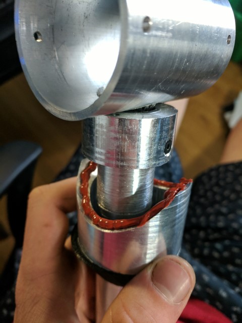
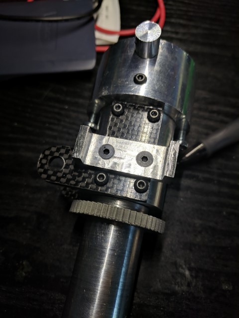
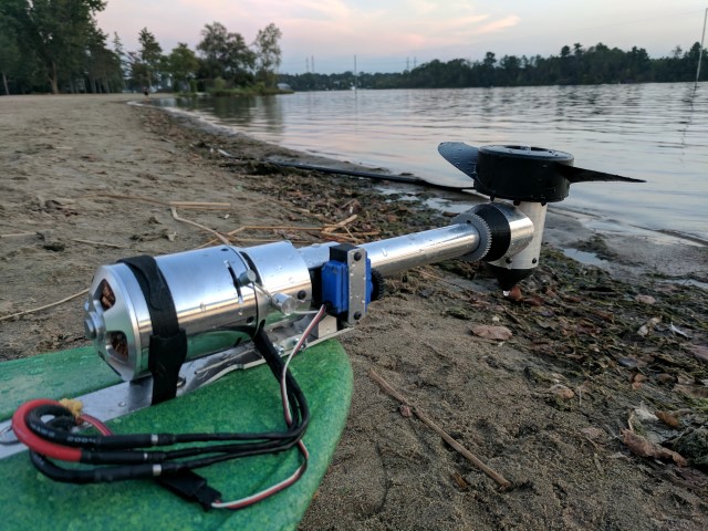
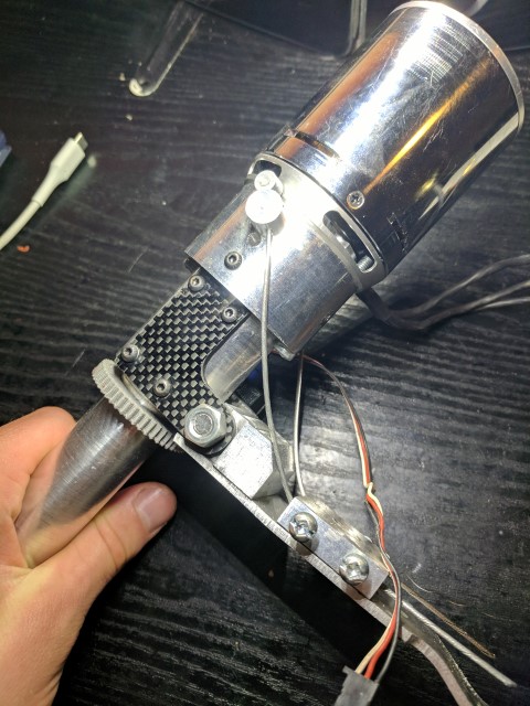
Left: Fully assembled minus the prop. Right: Tension cables keep the outboard upright
Moving upwards, the two cables attached just below the motor serve to counter the prop’s thrust moment. Holding them in place is another block of aluminum with through-holes and two 8-32 screws on either side which clamp the cables to the retaining block. Originally, M3 screws were used but they couldn’t be tightened enough to prevent the cable from slipping under high loads. If you look closely in the ‘First test’ video, you can see the assembly tweaking over when I apply throttle. There is a convenient drain plug hole which allows a nut and washer to be put inside the kayak and tighten the retaining piece directly against the hull. The mounting plate can be made from a thinner material because it doesn’t have to deal with the bending moment of the prop. Still, I think I will redesign the cable retaining block and pivot pin block to be one piece, with high sidewalls joining the gap that exists where the tension cables exit. The current design works for longitudinal thrust forces, but doesn’t accommodate lateral ones very well. (eg when the kayak is turning).
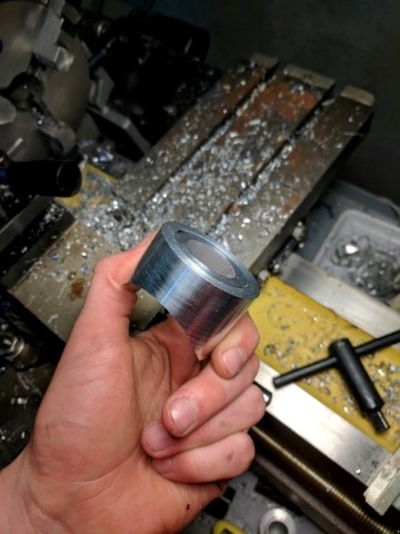
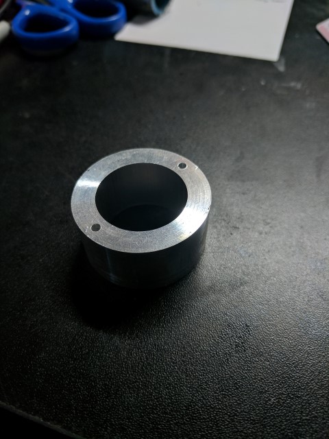
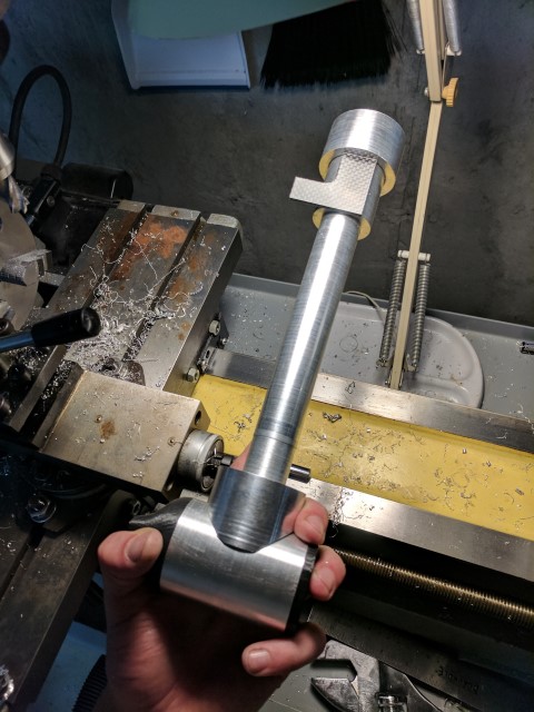
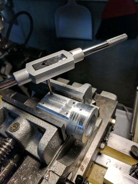
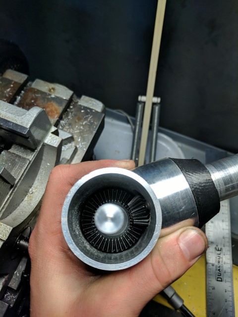
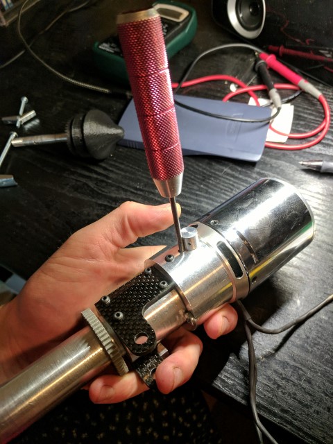
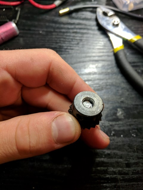
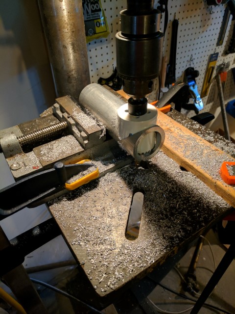
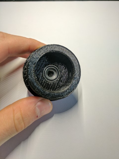
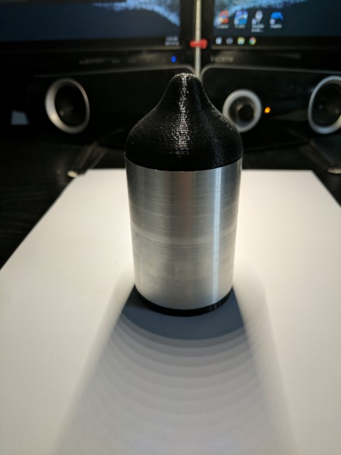
Lastly, the motor is secured with M4 screws which go through the entire length of the collet. I was super lucky that the motor diameter happens to match the 1.5” diameter of the collet, and that the mounting hole locations of the motor match the center of the collet sidewall, giving it a clean appearance. A small hole was drilled about a half inch below the motor, allowing me to stick an allen key in and tighten the drive shaft setscrew. Overall I’m incredibly happy with how the hardware came together and can’t wait to test it on the water!
Electronics


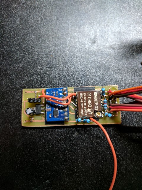
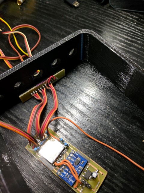
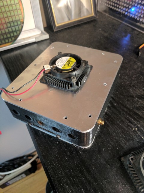
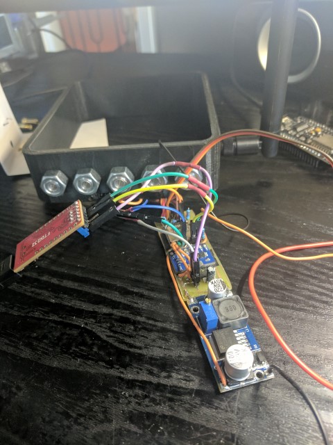
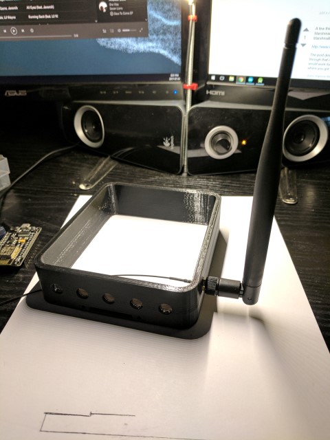
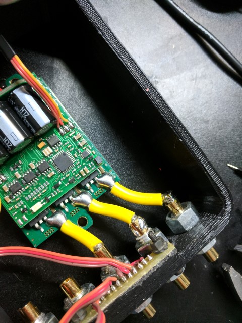
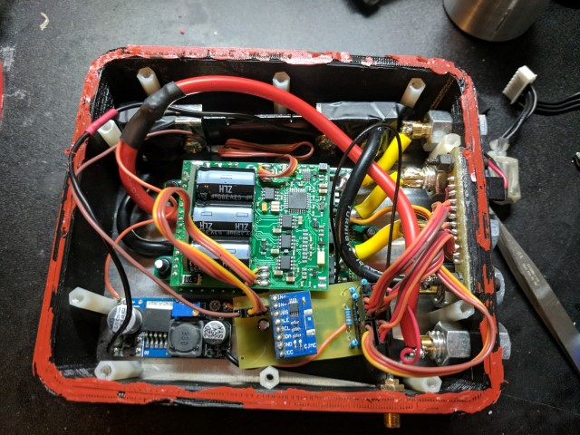
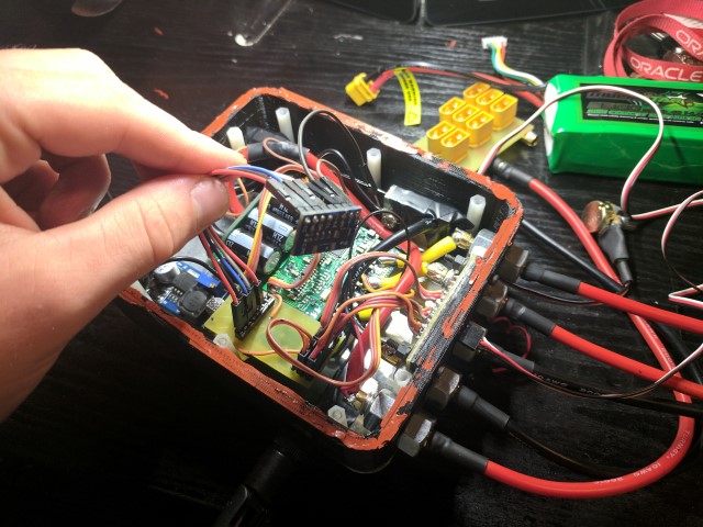
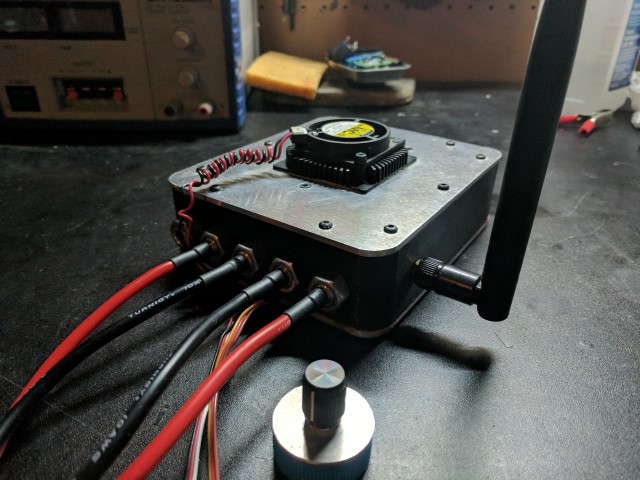
Inside of the Controller Housing. Wiring was thankfully cleaned up before final assembly.
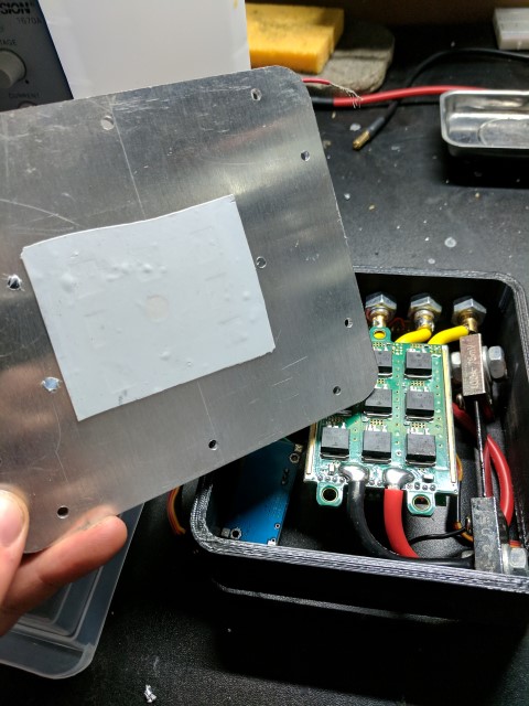
Apart from being able to drive the motor, the electronics in this black box are also responsible for controlling the steering, taking in power and temperature telemetry, and creating a wifi hotspot for two way communication with my phone. I’ll begin with the simplest component- the electronic speed controller. It’s the large green piece with fat wires going into it. As explained earlier, it’s essentially a variable frequency inverter that uses large FETs and switching circuits to turn the DC voltage from the batteries into 3-phase AC for the motor. It has it’s own microprocessor on board and takes commands in the form of a PPM signal, which is the standard in the R/C industry for controlling ESCs and servos. The ESC is mounted to the aluminum top plate and the FETs make direct contact to the surface through a thermally conductive pad. A CPU cooler mounted on the other side of the plate further helps dissipate heat. This solution has worked well enough that even during long runs, ESC temp never goes higher than 10-15 deg above ambient.
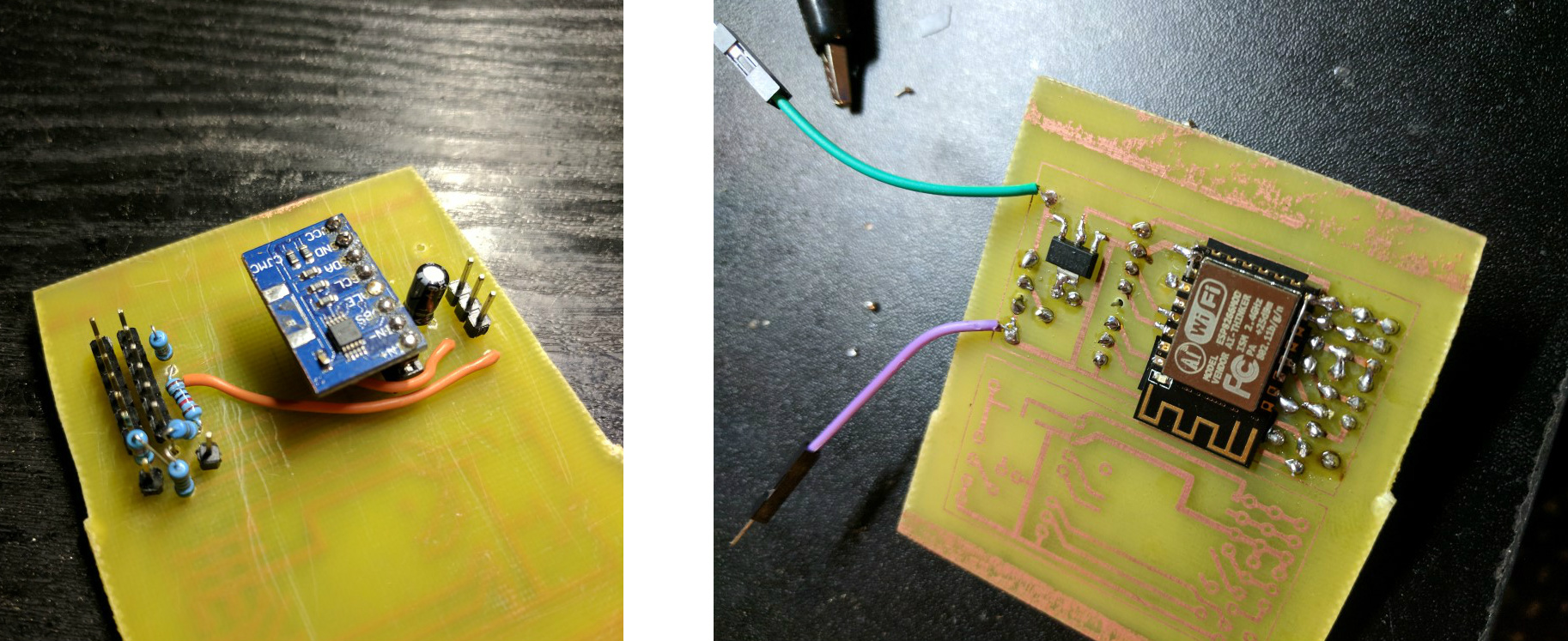
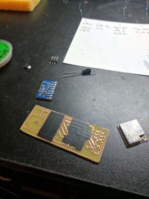
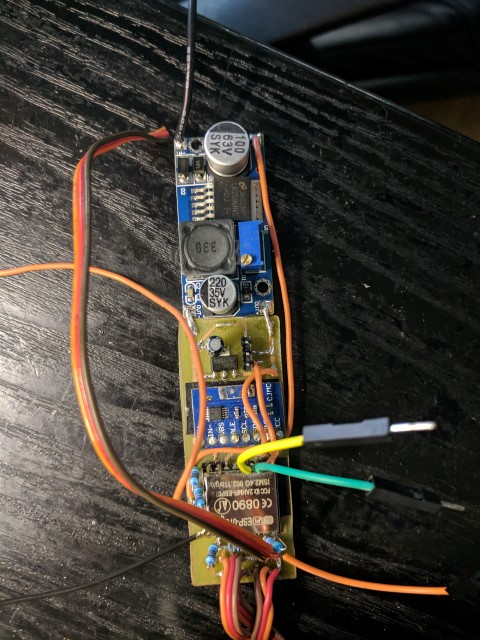
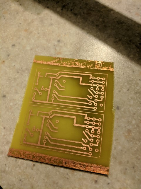
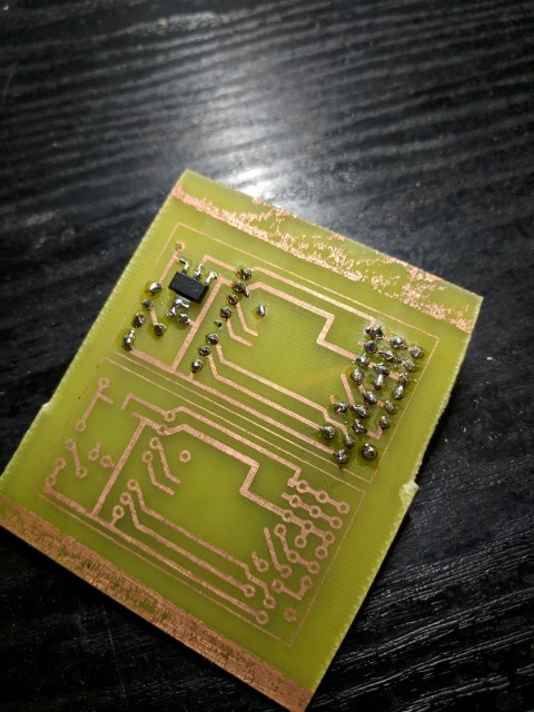
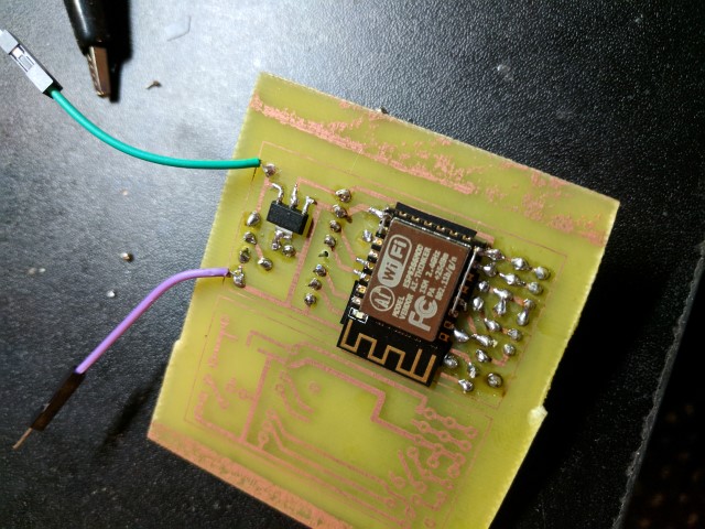
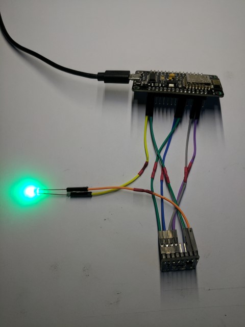
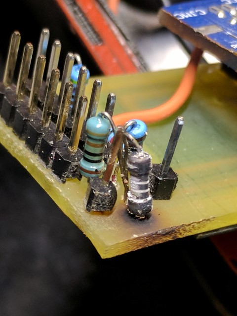
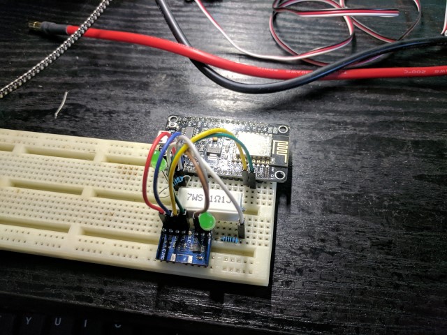
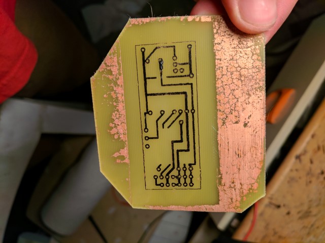
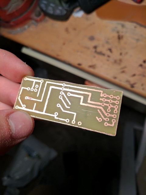
Prototype pcb. Would be nice to get these made professionally.
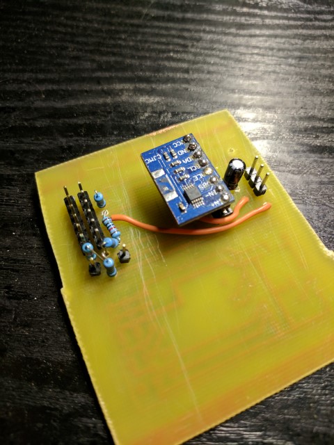
Next is the controller controlling the controller. I chose an ESP8266 board as the brains of this project because it’s small, cheap, and has tons of libraries and dev support. I’ll talk about the software in my next post. From a hardware perspective, it’s connected to two DS18B20 sensors for ESC and battery temperature monitoring, has two outputs dedicated to PPM signals for ESC and steering servo control, analog input for manual potentiometer throttle control, and i2c communication with an INA226 digital voltage/current measuring chip. The DS18B20 were chosen as temp sensors because there’s already an existing library that works with the ESP8266, plus they can be wired in parallel (!!!) through the oneWire protocol. I should take a second to mention that there’s two voltage regulators. The first is a high voltage switching regulator that drops the voltage from around 50v to 6v. Unlike a linear regulator which just consumes the waste energy, a switching regulator switches on and off very quickly and uses support components to smooth the output voltage. Linear regulators are much simpler and require less space, but with such a large voltage difference they would be extremely inefficient. I found it was actually cheaper to buy a pre built circuit board with all the support components rather than building my own, so that’s what the blue rectangular circuit board does. The 6v line is intended for powering the servos, fans, and esc. The rest of the components get 3.3v output from a linear regulator. 6v - 3.3v gives a voltage difference of just 2.7V which is easy enough for a linear regulator that is only powering some microcontrollers. Voltage and current measurement is done by the INA226 current sense chip. Across from the controller electronics is a very low ohm resistor, called a current shunt. It’s calibrated to measure exactly 75mV when 100A are flowing through it. The INA226 feeds this through an op-amp, and when calibrated correctly in software can return ultra-high accuracy voltage, current, and power information, all through the digital i2c interface.
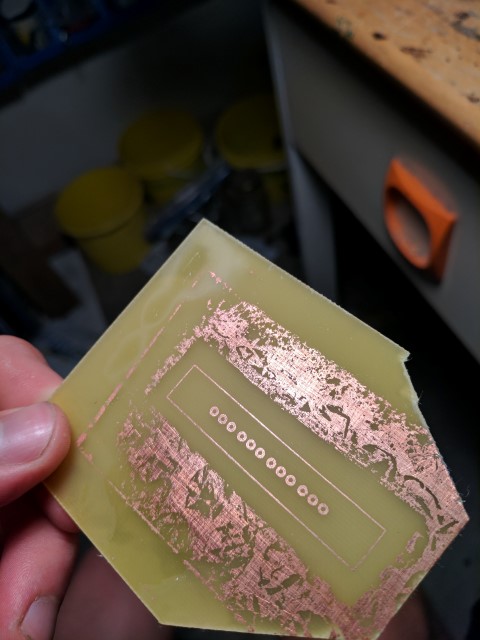
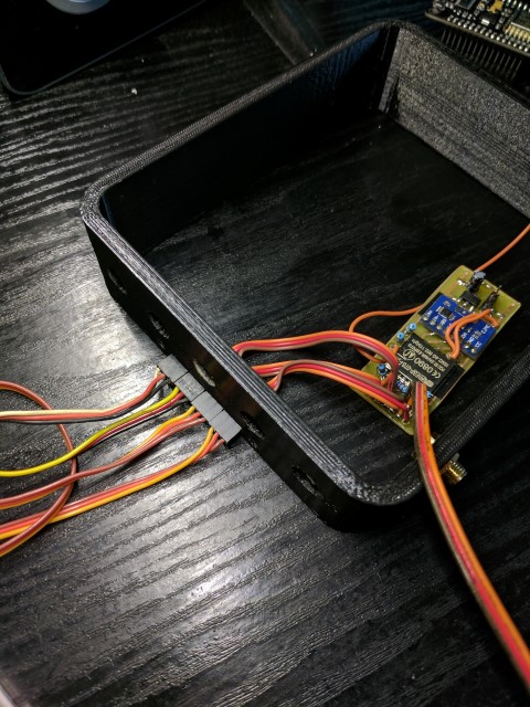
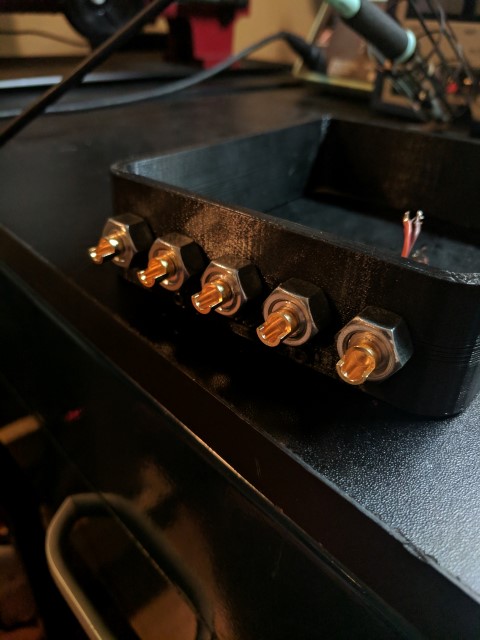
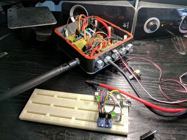
Lastly, I created a little circuit board design on Eagle and used the laser-toner method to print it out. The result was good and I’m really glad I put all the connections on headers because it made swapping out the boards for revisions much faster. All the external connections to servos, fans, etc go to a separate header board which is mounted to the enclosure and watertight. In fact, the entire enclosure is designed to be watertight. I can only hope that I never have to test this too thoroughly.
Software
The software is what sets this project apart from others. The ESP8266 runs an Arduino program that manages all of the core functionality of the electronics. I looked into using Lua or even Espruino, but you can’t match the libraries and support that the Arduino platform provides. Setting up the temperature sensors and servo/esc control was trivial thanks to existing libraries. One of the bigger hurdles was sending and receiving low-latency data over wifi. The existing http server library simply polls for new connections in it’s main loop. This results in terrible response times in the order of 500+ ms in some cases. The solution is to use the Espressif SDK’s native callback functions. Writing all this low-level code from scratch would be an absolute nightmare, but luckily I found a nice web server .C file in Espressif’s own github repository. It contained all sorts of web server functions, so I took those that were essential to sending, receiving, and parsing data and frankensteined them into my own Arduino library. A few setter and getter methods later, and the main Arduino program can cast data to the library’s variables where an incoming request triggers a callback function and sends it as a json string. Incoming steering and throttle data from my phone is transmitted through parameters in those same get requests that return telemetry data from the controller. The median response time is around 10-15ms, however there are a few outliers that slow things down. Still, 20 requests per second is possible, allowing reasonably smooth throttle and steering control. (Looking back, sending packets over UDP would have been an easier solution and I may abandon the TCP method in favor of it.) Source Code
At this point I found out that there was not yet a library for communicating with the INA226 current sense chip which compiled on the ESP8266. I have written a very simple one that takes out the guesswork of screwing with calibration values and just works. Source Code
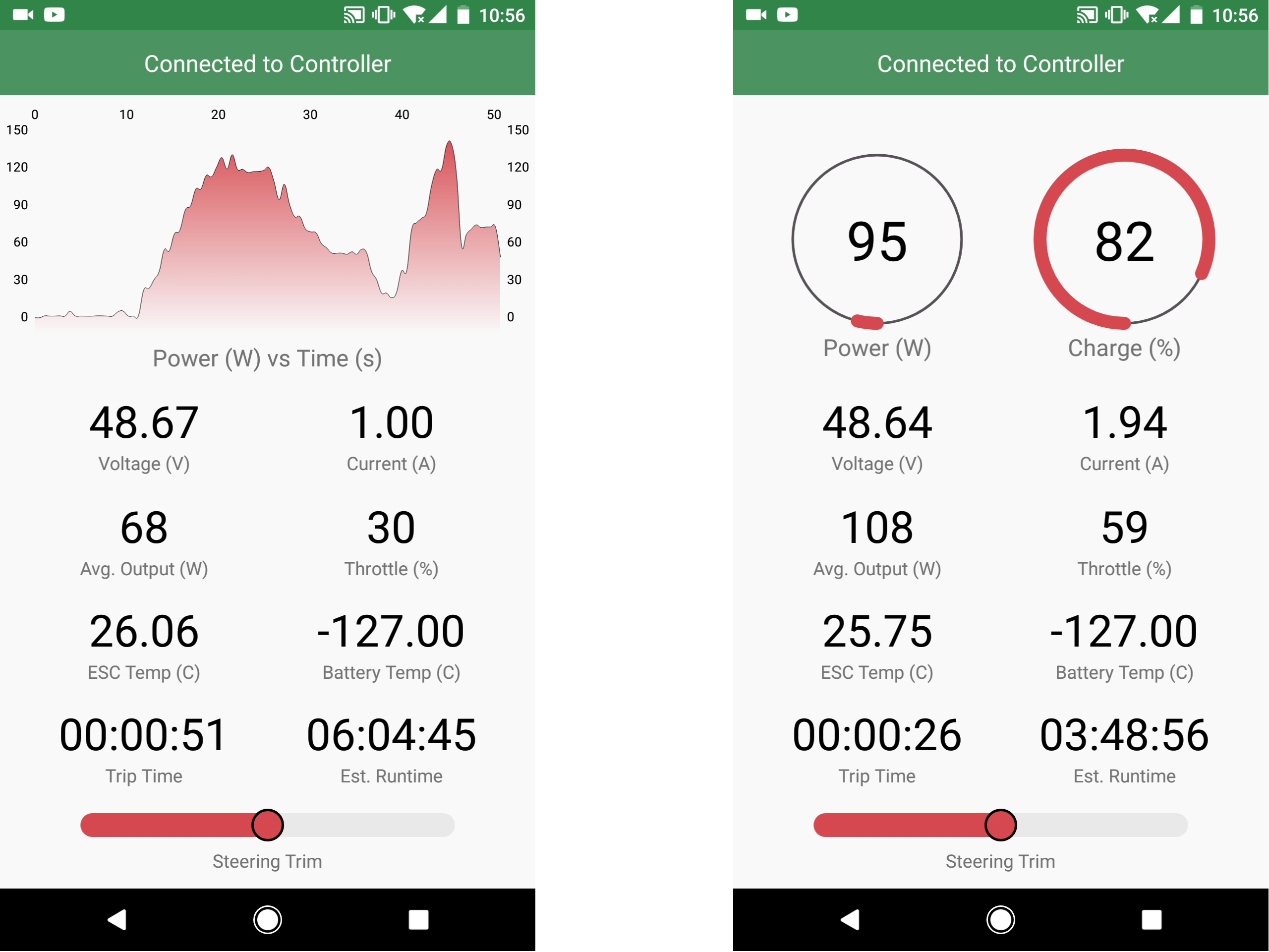
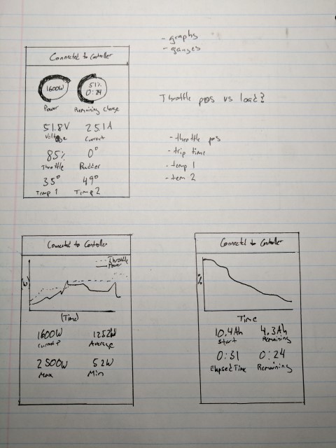
Main screen of the Houston app
An Android app seemed like the most logical method of viewing telemetry and controlling the kayak when required. Modern phones have gobs of processing power and include all the sensors you could ever ask for. “Houston” is the app I developed to serve this task. Being the first real Android app I’ve written, I spent more time rewriting the abhorrent parts into slightly less terrible versions. Also, there are always at least a half dozen ways to accomplish anything, but stack exchange (and sometimes google themselves) can never agree on which is best. In portrait mode the phone displays various telemetry data and throttle is controlled by a potentiometer directly connected to the controller. This use case is for when you’re actively sitting in the kayak and cruising around. I’m particularly happy with the power graph and estimated remaining runtime calculation, which become really useful while doing longer trips. When flipped into landscape, the phone enters “control mode” and you have control over the steering by phone tilt and throttle via the slider. This allows you to get out of the kayak and use it as an incredibly high power/weight ratio rc boat. Thanks to the long range antenna on the ESP8266, over ½ km of range is possible. Source Code
App Demo
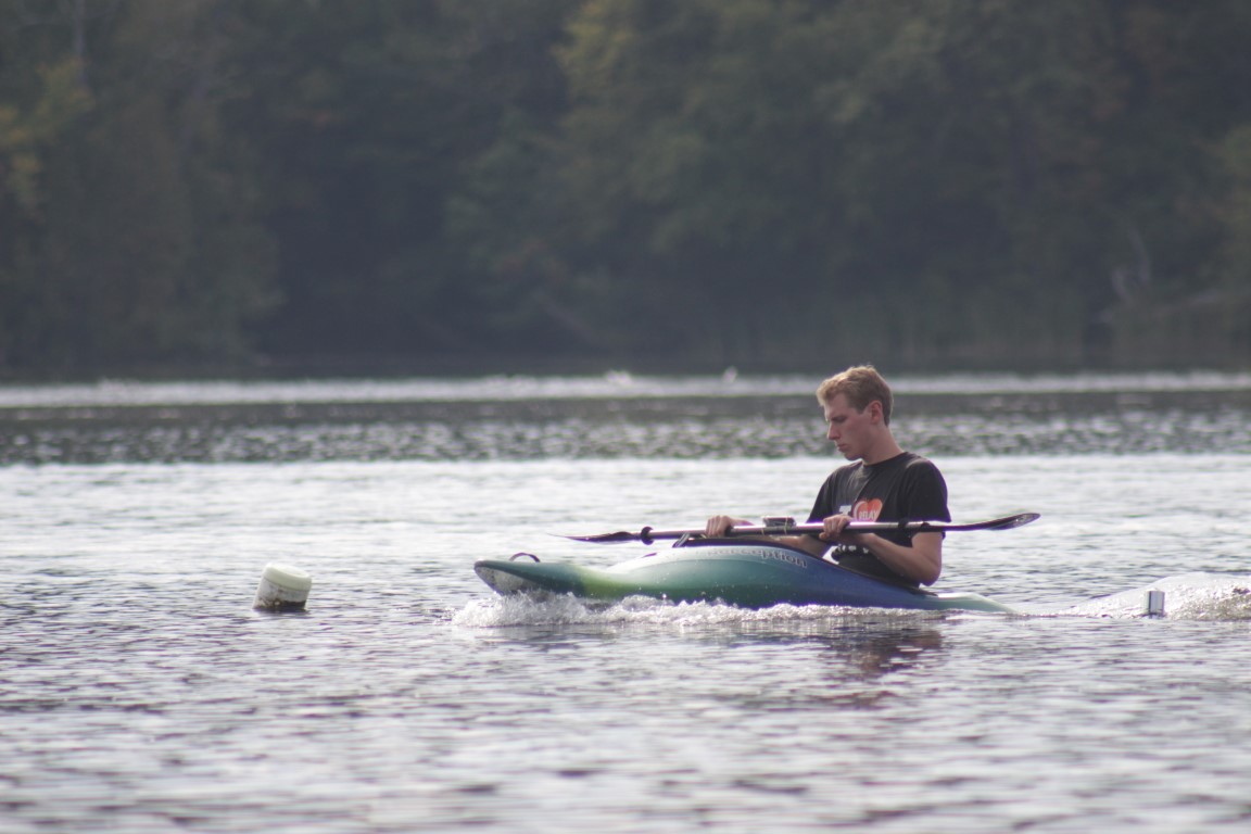
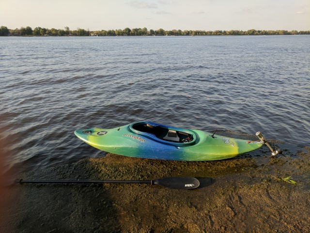
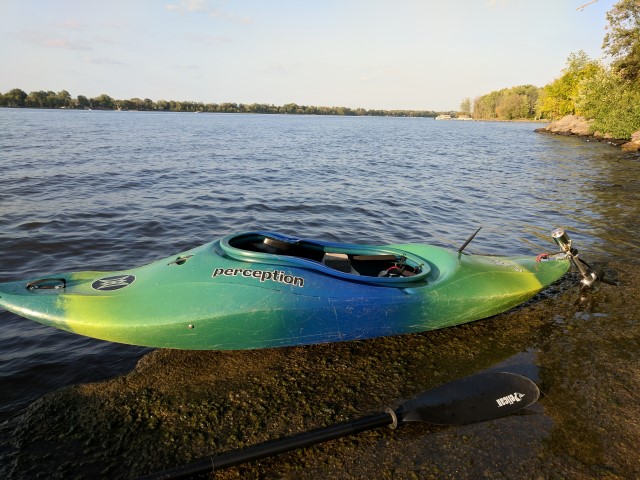
First Test
The end of summer was nearing and it was time to finally get the Kayak out on the water. After arriving at the beach and and triple checking the connections, I set out on its maiden voyage. For a couple seconds it looked like everything was going well, and then I raised the throttle and the driveshaft promptly sheared, leaving me paddling back to shore in shame. Still, it was not a total failure. The test had shown that all the electronic systems were working and the telemetry looked good. As for the driveshaft, it failed right where it mated with the bevel gear. The gear had some extra material so I later bored it out and fitted a larger diameter shaft, solving that issue.
First Test: My dad showed up for moral suppport
Subsequent Testing
The next few tests all revealed small problems that had to be ironed out. Broken set screws, stripped servo gears, and leaky driveline casings were at fault for the premature endings of several of my tests. On one occasion I brushed my hand on the throttle pot while getting out of the kayak, sending the motor into full throttle while the propeller dug into the sand. This caused some significant damage to the bevel gears and meant that in subsequent tests, I could not push over 500W before the gears started to slip. (Previously I had seen numbers up 2500W in telemetry) This is the current state of the kayak until I receive new bevel gears in the mail. On the bright side, this has allowed me to do lots of testing at low power levels. It seems that the kayak is most at home cruising around 300W output power. This allows for a speed similar to the row boats which frequent the section of the Rideau canal on which I test. Most surprisingly, I can get a solid 1 ½ to 2 hours of run time like this. If I slow down to the crawling speed of a regular canoe or kayaker, 3+ hours of runtime is possible. Overall I am quite satisfied with this but can’t wait to get the new gears so I can test what it’s like when the motor is pushing 3.5 HP.
Short POV clip while the Kayak is cruising along
Next Steps
This project has been an amazing learning opportunity and I’m not quite finished with it yet. The changes for version 2 will be aimed at making it easier to use and more reliable. Currently I have in mind to redesign the lower driveline casing to make it easier to assemble and more waterproof. Also the controller enclosure is completely overkill and can probably be shrunk by 30-50%. I will continue to update the blog as much as possible as developments are made. Thanks for taking the time to read through it!
Build Gallery
Testing Gallery